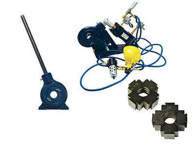
Brass Ferrule Crimper Operating Instructions
and Die Sizing
We Offer a Manually Operated Crimper – 5111A and an Air Operated Ferrule Crimper 1765A. Below are Instructions for the Manual Version Crimper.
The 5111A Ferrule Crimper is Hand Operated. It is used in a Fixed Location for Small Production Runs or Mounted on a Carrier as a Mobile Hose Repair Unit. The 5111A Ferrule Crimper is Designed for the Production or Repair of Hoses Using Light or Medium Weight Ferrules and Stems for Air or Water Hose. Read on to Learn more about Hose Crimping Ferrules.
Operation:
- Install Proper Ferrule and Stem onto Hose.
- Place Assembly into Opening Between the Crimping Dies and Pull Handle Until Crimping Dies Contact Ferrule. A Steady Pull on the Handle Will Bring the Dies Through Center Completing the Crimping Operation.
Die Change:
- Remove Wing Nuts and Lock Washers. Die Holder Plate can now be Removed Exposing the Crimping Dies as Well as the Die Holders Links and Their Pins.
- Crimping dies will Slide in and Out of the Mating Dovetails Freely.
- All Crimping Dies are Stamped with Their Part Number. When the Die Holder Plate is Removed, this Number is Visible on each Die. When Changing Dies, be sure to Install each Die with the Numbered Side Facing the Die Holder Plate. This is Very Important when Using Ribbed Dies for Proper Rib Orientation.
Maintenance:
The 5111A Ferrule Crimper is Greased at Time of Assembly. Periodic Inspection, Cleaning and Greasing of All Parts is Necessary. Use a WD40 Type Spray.
Plain and Ribbed Die Sizing Information
| Ribbed SKU | Plain Die SKU | Ferrule ID (in) | Stnd Ind Part # | Bore/Crimp Dia. (in) |
| R41 | P42 | 0.478 | 4750 | 0.450 |
| R40 | P40 | 0.500 | 7322 | 0.475 |
| R39 | P39 | 0.528 | 7323 | 0.500 |
| R39 | P39 | 0.528 | 7324 | 0.500 |
| R37 | P38 | 0.562 | 7325 | 0.525 |
| R36 | P37 | 0.593 | 7326 | 0.550 |
| R35 | P36 | 0.625 | 7327 | 0.575 |
| R34 | P35 | 0.656 | 7328 | 0.600 |
| R33 | P34 | 0.687 | 7329 | 0.625 |
| R31 | P32 | 0.718 | 7330 | 0.675 |
| R31 | P32 | 0.718 | 7330B | 0.675 |
| R30 | P31 | 0.750 | 7331 | 0.700 |
| R30 | P31 | 0.750 | 7331B | 0.700 |
| R29 | P30 | 0.781 | 7332 | 0.725 |
| R29 | P30 | 0.781 | 7332B | 0.725 |
| R28 | P29 | 0.812 | 7333 | 0.750 |
| R44 | P45 | 0.380 | 622 | 0.350 |
| R44 | P44 | 0.400 | 619 | 0.375 |
| R43 | P44 | 0.410 | 620 | 0.375 |
| R41 | P42 | 0.450 | 769 | 0.425 |
| R40 | P41 | 0.500 | 624 | 0.450 |
| R39 | P40 | 0.525 | 625 | 0.475 |
| R38 | P39 | 0.548 | 626 | 0.500 |
| R37 | P38 | 0.564 | 3588 | 0.525 |
| R37 | P38 | 0.575 | KK | 0.525 |
| R36 | P37 | 0.600 | JJ | 0.550 |
| R35 | P36 | 0.625 | II | 0.575 |
| R34 | P35 | 0.650 | HH | 0.600 |
| R34 | P34 | 0.675 | GG | 0.625 |
| R31 | P32 | 0.725 | EE | 0.675 |
| R30 | P32 | 0.750 | DD | 0.675 |
| R31 | P31 | 0.775 | CC | 0.700 |
| R28 | P29 | 0.800 | – | 0.750 |
| R27 | P28 | 0.825 | – | 0.775 |
| R26 | P27 | 0.850 | Z | 0.800 |
| R25 | P26 | 0.875 | 7244A | 0.825 |
| R24 | P25 | 0.900 | 5029A | 0.850 |
| R23 | P24 | 0.937 | 7242A | 0.875 |
| R21 | P22 | 0.975 | 5028A | 0.925 |
| R19 | P20 | 1.025 | 7114A | 0.975 |
| R13 | P14 | 1.175 | 7088A | 1.125 |
| R18 | P19 | 1.050 | 3605 | 1.000 |
| R16 | P17 | 1.100 | 5027A | 1.050 |
| R15 | P15 | 1.150 | 7104A | 1.100 |
| R11 | P12 | 1.225 | 875-K | 1.175 |
| R9 | P10 | 1.275 | 875-I | 1.225 |
| R4 | P5 | 1.400 | DD | 1.350 |
| – | P1 | 1.500 | 1500 | 1.450 |


